In the era of Industrial IoT (IIoT), smart devices are finding homes in places we hadn’t thought of. They could be installed in factory production, or in some remote area, ostensibly to sense and/or control. Whenever the smart device crashes, the whole operation could come to a stop.
To rectify this, traditionally, technicians are dispatched to these areas, usually just to restart the equipment. It not only wastes technicians’ time traveling back and forth, but also leads to long device downtime and potentially lost revenue. For this type of simple reset or reboot, a watchdog timer would swiftly solve this problem.
A watchdog timer is one of the more common devices designed into an embedded system, and they’ve been in use as long as embedded systems have been around. Essentially, the watchdog timer is hardware, either standalone or integrated within another device, like an MCU, that can automatically detect software anomalies and reset the processor if any anomalies occur. A watchdog timer is sometimes called a computer-operating-properly (COP) timer, or simply a watchdog.
To ensure the device’s operation, a fault and associated reset would be handled by a human, in theory. But in reality, that’s not possible, because the system needs to be watched 24/7/365, the action needs to occur very quickly, and the system may be housed in a remote location.
Windowed and Non-Windowed Watchdog Timers
In general, there are two types of watchdog timers: windowed and non-windowed. Both act in a similar fashion, causing a reset when invoked. The differences between them are that the windowed watchdog also causes a reset if the timer goes off too soon.
The watchdog timer is based on a counter that counts down from some initial value to zero. The embedded software that it’s watching selects the counter’s initial value and periodically restarts it to prevent it from timing out (reaching zero). If the counter ever reaches zero before the software restarts it, the software is presumed to be malfunctioning and the processor’s reset signal is asserted.
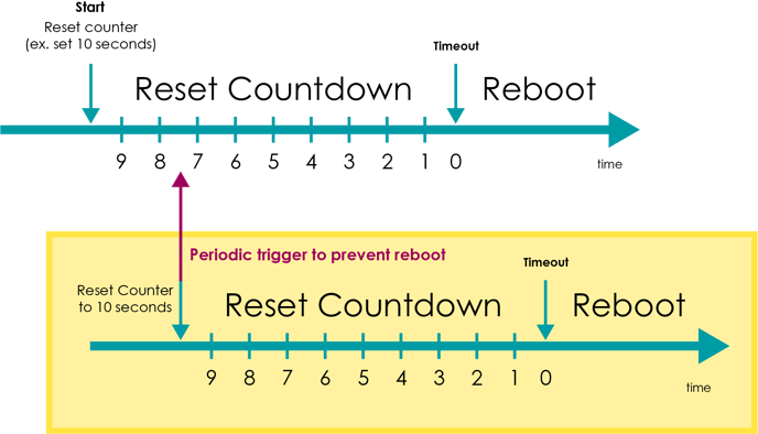
In the figure, you can see how the watchdog timer counts down, and then resets (likely rebooting the system) when it reaches zero, thereby indicating a fault has occurred.
An anomaly might occur when there’s a temporary hardware fault or if the software contains a bug or otherwise goes askew. Typically, where a fault is detected, the processor (and the embedded software that it’s running) will be restarted as if a human operator had cycled the power. However, other corrective actions can be taken is so deemed by the system’s design team. Such an action could be to place the computer in a safe state and/or reboot the system.
It's common today to find that watchdog timer embedded directly into the host microprocessor, significantly easing the design process. Alternatively, it could reside in a nearby IC that connects directly to the processor. There are cases where it’s actually on a separate board, but that scenario is rare.
Three Modes of Operation
In typical use, the watchdog timer can operate in one of three modes:
- Mode 1: When a computer malfunction occurs, it is reset and put back into operation
- Mode 2: When a computer malfunction occurs, the watchdog timer pin is pulled high
- Mode 3: When a computer malfunction occurs, the watchdog timer pin is pulled high and it issues a non-maskable interrupt (NMI)
An aspect of the watchdog timer that must be considered is when the microcontroller enters a low-power or sleep mode. The watchdog timer itself goes into a low-power mode, as it’s not needed if the processor is not in use. To handle this, the timer typically stops and restarts back at its initial count when the processor enters and exits from deep sleep.
Further, sleep mode is typically defined as where the CPU and the clock source and any peripherals that reference that clock are disabled. This would be the lowest power mode. Idle mode, which is also low power but not as low as sleep mode, is where the CPU is disabled but the system clock continues to operate. Peripherals may operate at this timer and can be optionally disabled.
One COM, Three Watchdog Timer Modes
%20R1.png?width=400&name=WL968-(Front200506)%20R1.png)
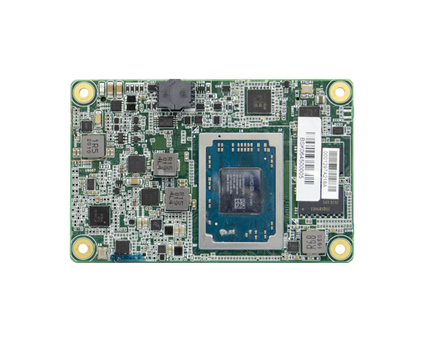
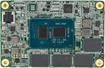
DFI’s WL968 is a COM Express 3.0 module that makes proper use of its watchdog timers. Designed around an Intel 8th Generation Core microprocessor, it’s suited for IoT Edge applications.
An example of a board that can handle all three watchdog timer modes is the DFI WL968. The COM Express 3.0 module is designed with Intel’s 8th Generation i3, i5, or i7 Core microprocessor. Other features of the WL968 include up to 64 Gbytes of DDR4 memory, various I/O interfaces, including AGA/DDI and LVDS, as well as DP++ that supports 4K by 2K resolution. Further expansion is handled through six PCIe ports, a GbE interface, and 12 USB ports (four USB 3.0 and eight USB 2.0).
Being in the embedded space, DFI knows how important long-life support is for its products. Hence, the WL968 offers 15-year CPU lifecycle support (based on Intel’s IOTG roadmap). Two versions of the module are available, one that operates in standard temperatures (0° to +60°C) and one that operates in an extended temperature range (-40° to +85°C).
Proper use of the watchdog timer can result in improved system performance and power efficiency, just as improper use can result in a “buggy” system. Let the experts at DFI help you untangle this web.
Products support COM Express 3.0 WDT
%20R1.png?width=114&name=WL968-(Front200506)%20R1.png)
.png?width=182&name=CH961(T201123).png)
_50.png?width=173&name=TGH960(F211228)_50.png)
.png?width=158&name=ICD970(F211221).png)
Need to place the antenna within the enclosure?